
Assembling DarkSoft CPS1 Multi Acrylic Plate
Warning!
- This is acrylic and plastic. Hands and screwdriver ONLY. Use power tools and something will break or strip.
- The protective film covering the acrylic sheet may (will) cause a charge when removed. Touch something metal that’s not your game hardware before you start handling the system. Nothing should happen but i’m not responsible if it does.
- Acrylic is plastic. So it will scratch. So I would avoid sharp objects around the acrylic (screws) until you’re ready for them.
Full Kit
Below is a photo of everything included in this Darksoft CPS1 Multi acrylic kit. If you're missing something please reach out using the contact page.

Also note as you open the plastic bags the plastic parts already have the correct screws already installed. This is a helpful reminder for the person assembling the kit on what screws are needed where. Plus it hopefully also makes sure we don't forget to include a random screw.


Let's get started. Find the 1/4 clear base plate and the two large bags of plastic spacers.

Remove the plastic spacers from the two bags and make note of the screws that are already installed. As you assembly the kit. You'll need to remove those screws before attaching. Please make note or separating the screws so you remember where they go.

Note the L1 and R1 marked on the inside face. This bag also includes a smaller bag marked "Dipswitch extender pcb spacers". Set this back aside for later.


The other bag has the rest of the spacers. Note the largest two in this bag are marked L2 and R2. A smaller includes a set of smaller spacers used as extra mounting support for the CPS1 A board mounting to the acrylic base plate.
Now remove the protective film from the base plate and begin installing the plastic spacers. Use the photo below for referencing where the different spacers go. The long round spacers won't be installed here. Note, don't overly tighten the base screws yet. As you want a little wiggle when sliding in the CPS1 A board.

When installing these spacers use the indented space in the round plastic foot to hold the screw head. So it lays flat.

Now at this point let's install the CPS1 A board. Make note on the right side both R1 and R2 spacers have a plastic arm that's in the way. It's easiest to slide the right side down first and then let the left.

Note there should be 5 mounting holes for attaching the motherboard to the spacers. The spacer R1 does NOT have a mounting hole. But just up the board an inch or so is one. See the close up photos below.
A long skinny screw driver will be your friend at this point with installing these 3/8 screws.


At this point find the bag of white plastic parts inside the LCD holder. The longest part is the JAMMA volume cover. You need to have it in place before we install the DarkSoft pcb.

Again. Find the longest part. Note that it has a rectangular base. Which should fit easily over the JAMMA volume nob near spacer R1.

Now we're ready to slowly slide the Darksoft multi pcb into place above the CPS1 A board.


Make sure both volume cover and all the pcb connectors line up before pressing the board down firmly in the the CPS1 A board.


Once pressed into place you can install the four 3/8 screws in to the four corners of the DS pcb.
Okay, now we're ready to stall the front JAMMA edge pcb that connects to both the A board and the Darksoft board.


Once pressed firmly into place, install 3/8" screws into the four corners. The holes should like up on the spacers.


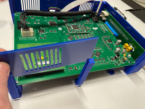
Now we'll install the blue acrylic sheet that covers this front JAMMA pcb. Note, you can leave it off if you're planning to use the micro dipswitch extenders by the stereo plugs. Or if it's in the way of a supergun JAMMA connection.


Use 4 black 1/2" screws to attach the plate. 2 on either side.


If you haven't already. It's a good time to connect the red and green wires back to the DarkSoft pcb. Note I like to route the wires before that blue spacer. As it'll keep the wires out of the way for the SD card slot in the acrylic plates later.

Now look for the LCD holder and install the LCD and the white button covers.


Attach it to the board.


Locate the 5 smaller blue acrylic plates and remove the pager backing. Follow the next several photos on where they need to be installed.


spin the setup around to the left side and install those side panels.
If you have a dipswitch extension pcb. Find that small bag you set aside earlier. Attach the for spacers to the pcb. Skinny side with the hole facing the front of the pcb. Matching the holes on the board. Note the parts with the cutout go on the bottom. So it can sit flush with the DarkSoft pcb.


Now to install the remaining side panel. Note, the following photos show the optional 40mm pc fan install and 12v/ground pin. Double and triple check your wiring. Your fan's wires may not match the one in the reference photos. Getting the 12v and the ground pins mixed up could do harm to your Darksoft multi board!


Now it's time to find that stereo volume cover and install it on the DarkSoft board.


Find the top blue acrylic plate and remove the protective film. Follow the next few photos to install the LCD holder using the black screws into the countersunk holes.


Now find the two volume covers and slide the blue plate into place.

Remove the protective film from the top clear plate. Taking extra care around the lettering. Slide it over the top blue plate and it's ready for the mounting screws.

It's also now time to add the long round spacers to the front left and right edges.

If you have a 3rd/4th player PCB you want to skip installing the right long round spacer. The top black screw has an alternative hole. See the following photos for reference. Also the R1 spacer includes a cutout for the 5V power line from this small pcb.


The last item and also completely option is the 1/4" acrylic handle. Note, USE THIS AT YOUR OWN RISK.
The screws are pre-installed. Make note of the orientation of the screws. As you want to install the plate on top of the base plate. With the screws going through the base plate and into the threaded inserts in the handle. NOTE, the threaded inserts are thicker on one side and skinny on the other. Which is why I said to make note of the orientation of the pre-installed screws.


Enjoy!