
Assembling Neo-Geo MV2F Plates
Warning!
- This is acrylic and plastic. Hands and screwdriver ONLY. Use power tools and something will break or strip.
- The protective film covering the acrylic sheet may (will) cause a charge when removed. Touch something metal that’s not your MVS before you start handling the system. Nothing should happen but i’m not responsible if it does.
- Acrylic is plastic. So it will scratch. So I would avoid sharp objects around the acrylic (screws) until you’re ready for them.
Step 1
Remove the metal shield from the top of the 2 slot motherboard. If yours has some rust like mine it might also be a great time to sand, clean and paint the metal cover.


Next set the metal shield aside.
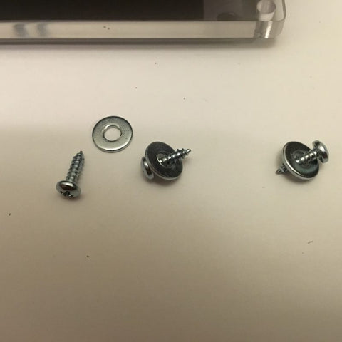
Open the hardware back labeled, “Base Plate Hardware” and find the pill shaped spacer and a set of 1/4″ screws.


Insert the 2 screws into on of the side of a cart slot. From the other side hold the pill shaped spacer in place and screw it down.


Repeat 3 more times so that each of the 2 cart slots has a spacer attached on either side of it. Also don’t tighten the screws down. Having a little play will help with assembly later.


Step 2
Find the 1/4″ acrylic sheet and remove the protective covering. To help avoid scratches I suggest using something non-metal (finger nail etc).

Depending on your area the acrylic sheet may have some static electricity. It’s best to remove the charge before handling the PCB.

Grab a 11mm round spacer, plastic leg and a 1/2″ screw. Attach to the acrylic sheet to one of the outer edge screw holes but NOT one of the 4 corners. Again leave a little play with the screws. Also note in the below photos the engraved side of the plate is facing down.


Flip the MV2F motherboard upside down (making sure to place on a non-conductive material). Set the acrylic sheet on top of it. Attempting to line up the holes.

Find the 4 round feet that match below and attach 1/2″ screws.

Screw them into the pill shaped spaces on the other side of the acrylic. Repeat for all for all 4 feet.


Flip over the PCB and base plate. Then find the 3/8″ screws and washers.
Place the metal shield back onto the PCB. Matching up the holes.

Attach the metal cover to plastic outer spacer you installed earlier with the 3/8″ screws.


Step 3
Open the hardware bag labeled, “Top Plate Hardware”. Disassemble the parts in the bag. Also set the 4 black screws to the side. In the photo below take note of the tall spacer. It only has threads on 1 side.

Attach the long screw to a plastic leg.


Select one of the 4 corners. Insert one of the 11mm spacers between the base plate and the PCB. Push the long screw through the spacer.

Attach the screw to the long spacer using the spacers threaded insert. Also not the long spacer has a flat surface. This side should face the metal shield.

Repeat for all 4 corners. Once complete, this would also be a good time to go back around and tighten all the previously installed screws.

Step 4
Find the 2 top acrylic plates and remove the protective material from both sides. Again beware any static charge created.

Also note these newly uncovered top plates will attract dust and hair like no other. You’ve been warned. lol

Find the last 4 washes included in the kit.

Place each one on top of the 4 corner spacers beside the metal cover. These washers are optional as they raise the acrylic plates slightly. So they may or may not be necessary depending on if your metal shield has any warping.

Place the acrylic sheets on top of your MV2F


Take the 4 black screws and attach to each of the 4 corns. Please don’t over tighten. Cracking or warping may occur. The below photo shows the plates being pinched slightly

Back the screw out slightly and it goes away.

Enjoy your completed
